If the world of networking was purely layer 2, segmentation would be a breeze as that ancient technology natively does wonders with separating frames based on their vlan membership.
Watch Video Tutorial:
This freedom to design a network to be heavily segmented comes to a screeching halt when a layer 3 device like a router is introduced into the equation.
Solving VLAN Segmentation Challenges with Virtual Routing and Forwarding
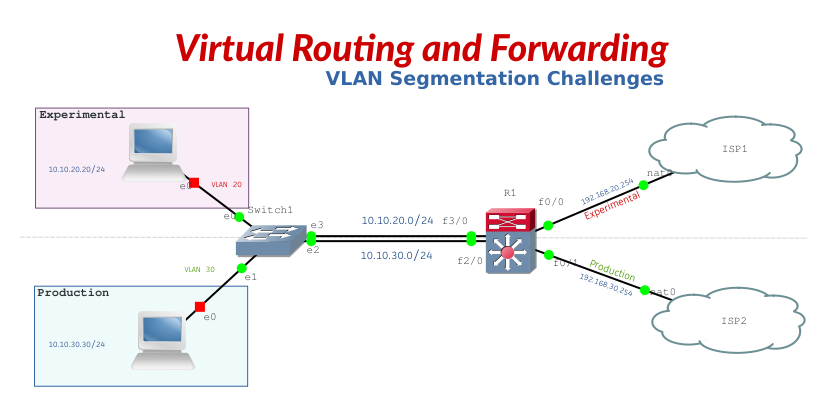
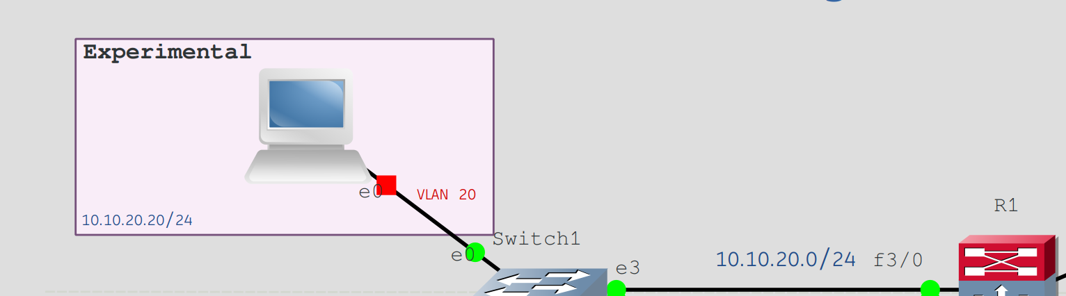
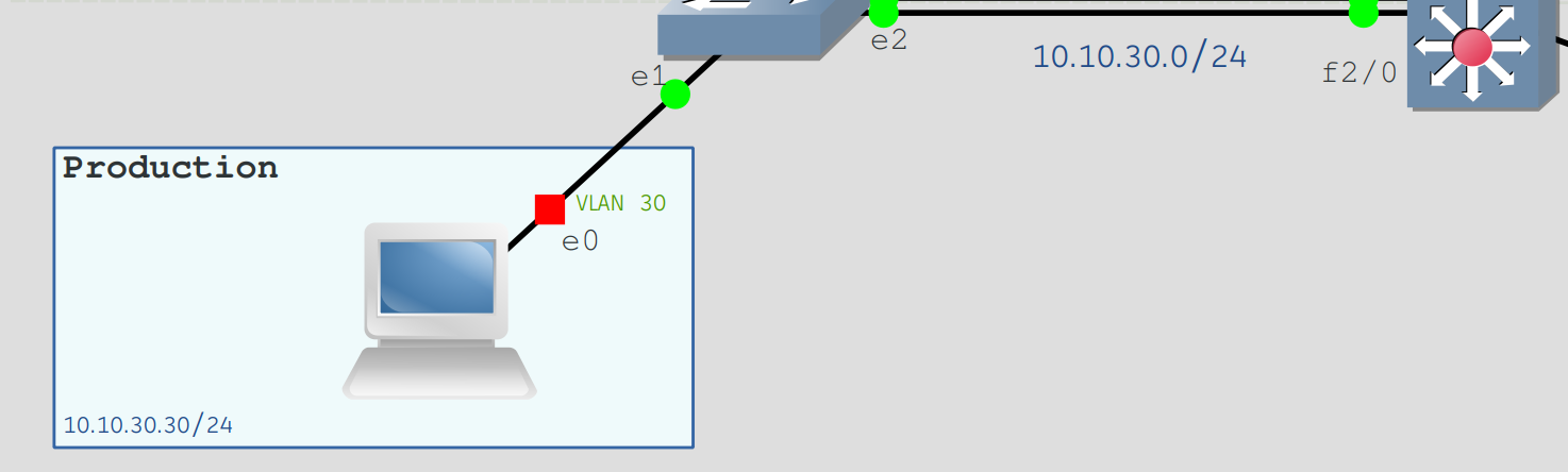
In this lab we have dedicated vlans for the experimental and production departments of our business. We clearly have separate functions for each department and will like to express that as well for the traffic sourced from these departments. As mentioned above, vlans work well on the layer 2 edge but these departments need access to the internet and as you can see, we have 2 customer premises equipment facing separate ISPs.
The router is great at getting all connected networks to talk to each other by default. This is normally done because “ip routing” is enabled which makes it a layer 3 device.
Scenario 1
We do not want traffic from Experimental to be able to get to Production for many reasons. Imagine Experimental have been diagnosing a compromised machine which may have a malware or ransomware, the last thing you want to see is that the traffic from that source is able to get to the Production network. With VLANS we can logically separate the departments but it becomes extremely difficult with routing and so VRF comes to save this challenge.
Scenario 2
Experimental have been known to use a lot of internet bandwidth as they are in the habit of uploading and downloading files to and from cloud platforms as well as web resources. We want our production traffic to be guaranteed as this is production sensitive, there are databases been written to from applications to the cloud. There must be guaranteed bandwidth at all times for Production traffic and what we do not want to see is bandwidth hogging by Experimental and so we have dedicated different ISP for each department.
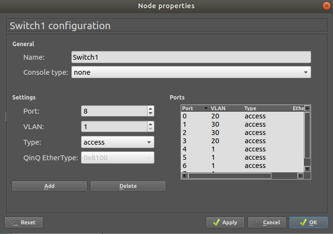
Let us begin by configuring our VLANS for Experimental and Production. I am using the default layer-2 switch in this GNS3 lab but the concept is the same for your standard Cisco switch.
Configure VLAN 20
Configure VLAN 30
VLAN Membership for Experimental and Production
Solving VLAN Segmentation Challenges with Virtual Routing and Forwarding

Let us configure our router to accommodate these departments;
Configure VRF Forwarding for Experimental
!
ip vrf Experimental
!
Configure Interface dedicated to Experimental
R1#show run int Lo0
!
interface Loopback0
 ip vrf forwarding Experimental
 ip address 1.1.1.1 255.255.255.255
end
R1#show run int f3/0
!
interface FastEthernet3/0
 ip vrf forwarding Experimental
 ip address 10.10.20.254 255.255.255.0
 duplex auto
 speed auto
end
R1#
Let's configure the ISP for Experimental
R1#show run int f0/0
!
interface FastEthernet0/0
 description "BNET ISP 1 Traffic"
 ip vrf forwarding Experimental
 ip address 192.168.20.254 255.255.255.0
 duplex auto
 speed auto
end
R1#
Configure OSPF for Experimental
R1#show run | section ospf
router ospf 1 vrf Experimental
 log-adjacency-changes
 passive-interface FastEthernet0/0
 passive-interface FastEthernet3/0
 network 1.1.1.1 0.0.0.0 area 0
 network 10.10.20.254 0.0.0.0 area 0
 network 192.168.20.254 0.0.0.0 area 0
Configure VRF Forwarding for Production
!
ip vrf Production
!
Configure Interface dedicated to Production
R1#show run int Lo1
!
interface Loopback1
 ip vrf forwarding Production
 ip address 2.2.2.2 255.255.255.255
end
R1#show run int f2/0
!
interface FastEthernet2/0
 description "Production Network Gateway"
 ip vrf forwarding Production
 ip address 10.10.30.254 255.255.255.0
 duplex auto
 speed auto
end
R1#
Let's configure the ISP for Production
R1#show run int f0/1
!
interface FastEthernet0/1
 description "CNET ISP1 Traffic"
 ip vrf forwarding Production
 ip address 192.168.30.254 255.255.255.0
 duplex auto
 speed auto
end
R1#
Configure OSPF for Production
router ospf 2 vrf Production
 log-adjacency-changes
 passive-interface FastEthernet0/1
 passive-interface FastEthernet2/0
 network 2.2.2.2 0.0.0.0 area 0
 network 10.10.30.254 0.0.0.0 area 0
 network 192.168.30.254 0.0.0.0 area 0
Since you have successfully completed the above steps, as a good practice, let us verify the configuration so far for Experimental and Production.
Show IP VRF Interfaces
R1#show ip vrf interfaces
Interface              IP-Address      VRF                              Protocol
Lo0                    1.1.1.1         Experimental                     up
Fa0/0                  192.168.20.254  Experimental                     up
Fa3/0                  10.10.20.254    Experimental                     up

Lo1                    2.2.2.2         Production                       up
Fa0/1                  192.168.30.254  Production                       up
Fa2/0                  10.10.30.254    Production                       up
Show IP Protocols for Experimental
R1#show ip protocols vrf Experimental
Routing Protocol is "ospf 1"
  Outgoing update filter list for all interfaces is not set
  Incoming update filter list for all interfaces is not set
  Router ID 1.1.1.1
  It is an area border router
  Number of areas in this router is 1. 1 normal 0 stub 0 nssa
  Maximum path: 4
  Routing for Networks:
    1.1.1.1 0.0.0.0 area 0
    10.10.20.254 0.0.0.0 area 0
    192.168.20.254 0.0.0.0 area 0
 Reference bandwidth unit is 100 mbps
  Passive Interface(s):
    FastEthernet0/0
    FastEthernet3/0
  Routing Information Sources:
    Gateway         Distance      Last Update
  Distance: (default is 110)
Show IP Protocols for Production
R1#show ip protocols vrf Production
Routing Protocol is "ospf 2"
  Outgoing update filter list for all interfaces is not set
  Incoming update filter list for all interfaces is not set
  Router ID 2.2.2.2
  It is an area border router
  Number of areas in this router is 1. 1 normal 0 stub 0 nssa
  Maximum path: 4
  Routing for Networks:
    2.2.2.2 0.0.0.0 area 0
    10.10.30.254 0.0.0.0 area 0
    192.168.30.254 0.0.0.0 area 0
 Reference bandwidth unit is 100 mbps
  Passive Interface(s):
    FastEthernet0/1
    FastEthernet2/0
  Routing Information Sources:
    Gateway         Distance      Last Update
  Distance: (default is 110)
Steps to Configure VRF-Lite End-to-End
- Create L2 VLANs at the edge of the network
and trunk them to the first L3 device –or L3 access - VRFs need to be defined on each L3 device,
Map the VLANs to a VRF - IGPs are configured for each VRF on each
L3 device - Trunks need to be configured to carry each
of the VRFs
Create sub-interfaces and map them to the
correct VRF - Traffic is now carried end-to-end across the
network maintaining logical isolation between the
defined groups